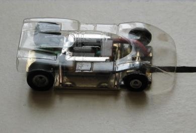
Gary Rider 1971 Riggen based chassis....
Modifying your Riggen to Upgrade Performance by Gary "The Geek"
Rider
This was my building approach for improving the Riggen Racer to competitive
levels in the early 70's, before
the brass pan a\fx racers took over. The objective was to add weight and move
it lower for improved handling, and to
replace the pickup system with a pianowire guidepin and phosphrous bronze shoes
for quicker cornering and easier
marshaling. Also to add bronze bushings to the rear axle for a smoother, more
solid gear drive and pin tube body
mounting for more secure mounting of the lightweight body.

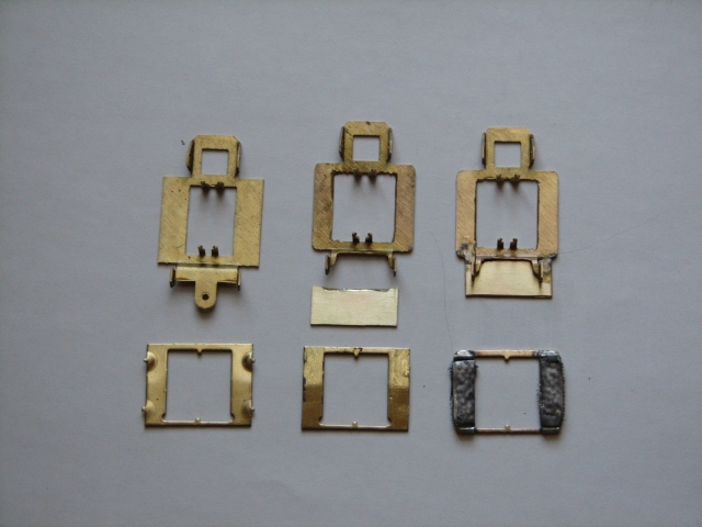
The Riggen on the left is a stock Riggen chassis and floater mounting bracket.
In the middle picture I have used
a Dremel cutoff wheel to enlarge the middle square hole to allow for the motor
to drop down level with the bottom of the
chassis. Also I have removed the guideflag support and cut away brass to allow
room to solder the guide pin and
room for motor lead wires in a later step. The middle picture also shows the
.032 brass piece added to the front
of the chassis, level with the bottom. The piece is 1" wide and .500"
long. Grind a 45 degree bevel where the middle
meets the main chassis, for better fit. Tack the top sides with solder, then
flip over and solder the edges together,
across the bottom, then smooth out the seam so everything is flat on the bottom.
You will also need to fit the motor,
and file the motor support tabs downward, with a round file, to allow the motor
to drop down flat with the bottom of the
chassis. The floater section has the bumps ground flat, then 1\16" pin
tubing added (at each corner), for body mounting,
then a layer of .035" soft lead epoxied between the pin tubes to give the
floater some weight for improved cornering.
Next, the axle holes need to be opened up for installation of the brass bushings.
Do this gradually with a drill and
bits, making sure that the alignment is square with the car and even with the
bottom of the chassis. I favor a flanged
brass bushing to make this an easier task. Open up the hole until the bushing
will fit into it, then we will carefully,
solder them in place. Next we will install the pianowire guide pin. A 1\16"
hole needs to be drilled on the centerline
of the car directly under the front axle line. This puts it at 1 1\2" from
the back axle. I take a longer piece of wire and
bend one end, leaving about 1\8". You need to use the dremel and make a
square corner, so that the wire will lay
flat on the top of the chassis, for a good solder connection. With the chassis
on a flat surface and the wire hanging
through the hole, you can solder it to the chassis. Check to make sure it is
straight, in both directions, before cutting
off the excess and grinding the bottom down, leaving 3\16" depth from the
bottom of the chassis.


(this car went to AF)
Around 100% the way I built them in 71. I would do a few minor things different
nowdays. I still like the guide pin and pickup system.
I set the depth for Aurora track, and do not know if your slots might be deeper???
Guide pin should be as long as possible, without dragging the bottom.
I would sometimes file the sides of the pin a little, if they catch at the track
sections. That's part of the tweaking, when the car first hits the track.
I'm going to shorten the current build slightly, to 2" in length.... all
off the front end. (by 1\8") (Which will move the shoes back, slightly)
I plan on making the floater with .064 brass outriggers to provide a little
more weight on the floater, for better handling.
I always added a little lead there, but the thicker brass will serve the same
purpose and appear cleaner.
Before racing, I always secured the motor with a touch of solder, at the back
motor mount, in order to prevent movement.
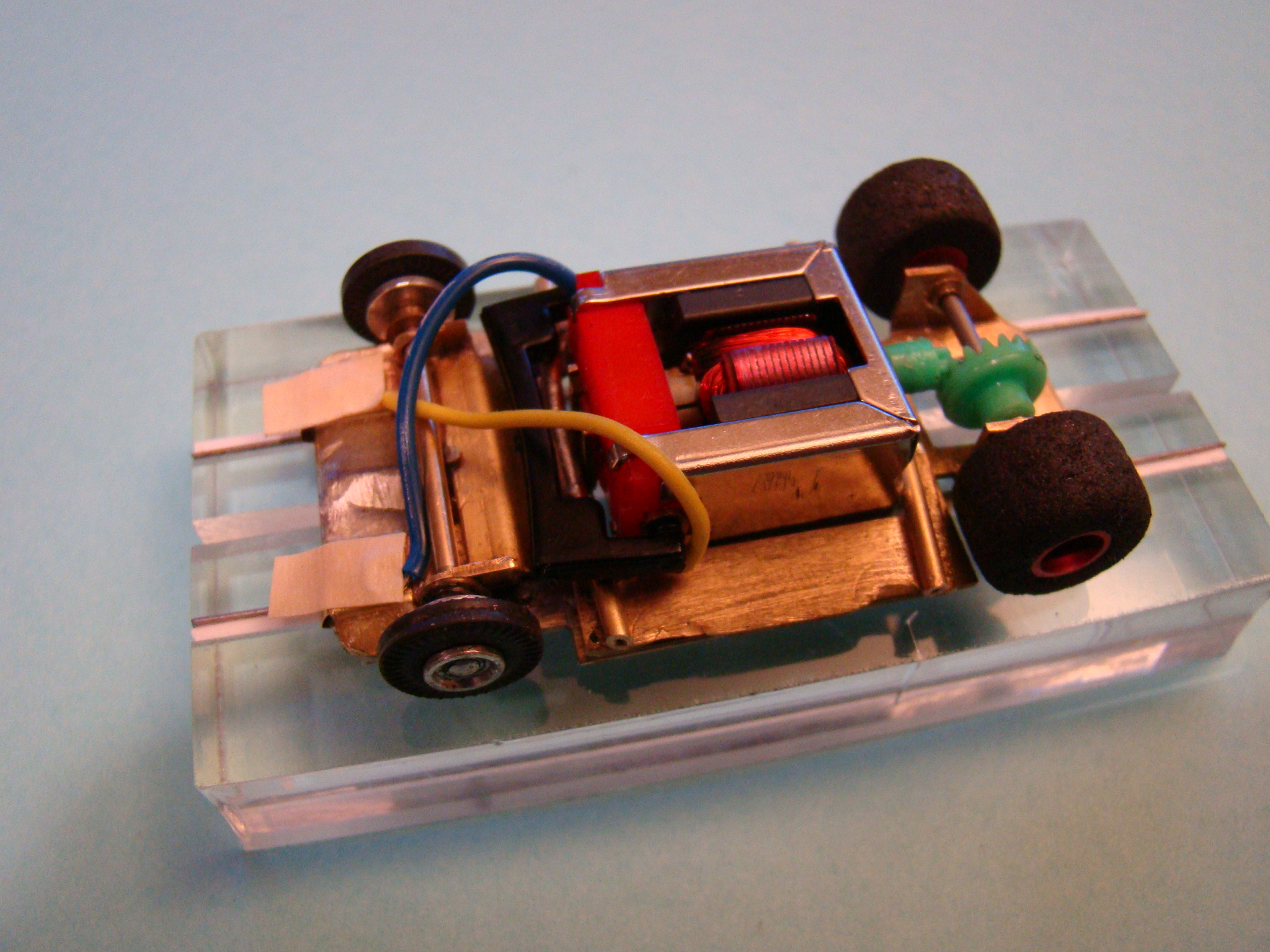
Used small flanged rear bearings and epoxied them to the frame after mounting
the TycoPro gear.
Most everyone was running black sponge from 70-72. My wheels must be TCP threaded
(was guessing they were Riggen) They had a red coating.


(this car came to me as test mule 1 for the Limited Edition....)
----------------------------------------------------------------------------------------------------------------------------


Test Car 1
TycoPro hop up gear set
Red anno TCP rear rims
Flynn Red Bell motor
---I replaced rears with a set of AJ's sponge that Rabbit dipped for me....


Test Car 2
Tyco Pro stock crown with hop up green pinion
shorter chassis front section
1/32 sili lead wire
Tyco Pro red arm epoxied motor----
Aluminum TCP rear rims
---I replaced with Cobramite sponge that Rabbit dipped for me


